KENT LASERS: LASER CUTTER ALIGNMENT PROCESS.
The following information is provided for educational reference ONLY. All repairs should be undertaken by a qualified engineer. The use of the following information is done so entirely at your own risk! Kent Lasers is an INDEPENDENT service provider and not affiliated with any machine brand or manufacturer.
KENT LASERS: CO2 Laser cutter: Prestige Series

Kent Lasers has made the alignment procedure for all of its machinery extremely simple, with all adjustments on Professional (and Prestige) series machines being obtainable from the FRONT of the machine; this means that once the system is installed and moved into position, the alignment can be undertaken easily without having to move, or gain access to the rear (or service panels) of the system! Simply open the lid as if you were loading materials and make all the necessary adjustments!
This makes the installation and servicing of equipment extremely easy!
For added convenience, a visible red alignment laser is combined with the main cutting beam. This gives the user a visual indication as the the aim and pitch of the beam. (as well as being useful for alignment of jobs and materials) This also means that Professional machines can be fully optically aligned in seconds WITHOUT even firing the laser!
This is a very useful feature, traditionally reserved for equipment carrying a much higher cost, and is installed as standard on our machine range.
The illustration opposite (and the "real-world" image above) demonstrate the principle on which our laser cutting platforms operate. This is know in the industry as a "flying optics" beam delivery system. This is so called because the laser light is reflected off three mirrors, two of which are moving in the X and Y direction.
The laser light is then focused through a lens onto your work-piece. It is therfore critical that these mirrors are configured correctly in order for your cutting system to perform efficiently.


To proceed with testing, a small amount of masking tape will be required, in addition to a 1.5mm Allen (hex) wrench and a fine-tipped pen. To begin, place a small circular dot on a piece of masking tape, torn to roughly a 2" length.
This piece of tape can now be affixed to the SECOND mirror, whilst the gantry is placed in the rear-most position of travel. Ensure that the dot on the masking tape is covered by the RED laser dot.
Please note that whilst the lid is open, the laser cannot fire; Professional and Prestige machines are inherently safe with dual redundant interlocks. With the lid open the laser is physically disabled, and the controller's laser output is inhibited.


The gantry (Y Axis) can now be moved to its maximum travel position (towards the front of the machine) and the location of the red dot checked.
This dot should cover the original pen marking exactly, with only the smallest of deviation. (Illustrated by the opposite image)
Please note that this is the second mirror, and that in order to effect a change in beam location, adjustments are always made to the previous mirror.
Please note that the aim of the laser onto the first mirror surface is set at the factory, and no user adjustments (from the laser tube) will be required for this optic.
Furthermore, fingerprints should be avoided on the mirror surfaces, and each optical element should be gently cleaned with a light solvent (such as IPA) and soft tissue, after adjustments have been made.
The mirror surfaces are however solid molybdenum and are very, very durable.

The same process can now be repeated with the tool-head (cutting head/nozzle).
The piece of masking tape can be re-used and the red alignment dot should remain in the same position at BOTH extents of travel to ensure the beam is parallel, and has no deviations.
The beam should enter the tool head aperture in the exact centre.


The above video shows how small adjustments of the beam location can be achieved by turning the 1.5mm hex adjusters on the mirror plate. To effect the above change, only a fraction of a turn is required, and great care should be taken not to over tighten the adjusters. Please remember that these set-screws are for adjustment, and do not require tightening until resistance is felt. The two larger bolts on the opposing corner of the mirror plate are for retention of the mirror itself, and should never be adjusted.

To finalise the X and Y optical alignment and calibration, the lid can now be closed, with the masking tape in place and the tool-head in the CENTRE of travel in the Y direction, and at maximum X travel. (X axis to far right).
The "laser" key on the machines key-pad can now be pressed, creating a small low-intensity pulse from the laser unit;
This will create a burn mark on the masking tape, which has been affixed to the beam input aperture on the tool head, to ensure that the red-dot location, and cutting beam are co-incident. (travelling in the same location)
This ensures that the alignment, which has been achieved with the red alignment dot can be fully utilised for cutting.
In order to finalise alignment of the laser, we must now check the alignment of the 3rd mirror;
This can be achieved by placing a small amount of masking tape on the bottom of the focus tube (the cylindrical tube which inserts into the body of the tool-head) and ensuring the beam hits in the exact centre of the tube-end.
Please note that this final test MUST be performed with the focus lens REMOVED!
It is also possible to utilise the red alignment beam to test the alignment of the 3rd mirror, and an actual firing of the cutting laser is not strictly required.

MAKING ADJUSTMENTS:
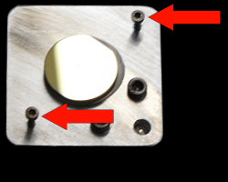
Adjustments can be made to the aim and pitch of the beam by gently (and slowly) rotating the adjustment screws as arrowed in the opposite image. These adjustments will change the position of the mirror plate, relative to the mirror post (bracket) therefore changing beam direction.
If it is deemed necessary to remove the focusing lens to check the aim of the 3rd mirror (installed on the top of the cutting head) the image opposite shows the sequence of parts, and their correct orientation for re-installation. From top to bottom we have:
Mirror adjustment plate. Tool-head body. Lens tube. Slew ring (for locking the nozzle in correct orientation). Focusing lens. Lens retainer (threaded). Nozzle and air-assist connector.

For further advice on any aspect of machine maintenance, please do not hesitate to Contact Us.